Plans task
- Introduction to the Plans Task
- Material Library and Palettes
- Creating a Floor Plan
- Surveyed Plan and Design Options
- Emitters
- Sources
- Hot Water Storage
- Ventilation Calculations in Heatpunk
- Sound Check (UK)
Introduction to the Plans Task
In the Plans task, you create your initial floor plan - the surveyed plan - and then create design options by placing heat pumps, cylinders, and modelling emitter upgrades directly on the plan.
With heat loss calculations fully integrated into the Plans task, you can clearly see where emitter upgrades are needed. The ventilation calculation and, for UK users, the sound check are also completed in this task.
Creating your surveyed plan
When creating a floor plan, the first step is to select or create your material palette. This palette determines the materials (radiators, walls, windows, floors, etc.) you can use to model the property. This can be edited at any stage.
You will be then prompted to complete the ventilation calculation.
Ventilation calculation
For Heatpunk UK/IE, choose from:
- Legacy MCS method / S.R.50-2021
- Standard method / BS EN 12831-1:2017 using assumed air permeability
- BS EN 12831-1:2017 using measured air permeability
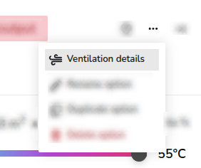
Once completed, you can edit the ventilation calculation by clicking click the ⋯ three dots in the top right corner and then selecting Ventilation details.
Creating floor plan
You will then be prompted to input the default ceiling height and complete the surveyed plan.
To build your plan, drag and drop elements (rooms, radiators, windows, doors) from the left-hand sidebar. As you build the plan and add emitters, you can view the heat loss, total floor area and W/m2 at the bottom of the right-hand sidebar. For details on the heat loss for individual rooms, click 🡥 See room details on the right-hand sidebar of each room.
Read more about creating a floor plan and how to speed up creating your floor plan by uploading architectural plans with Heatpunk Pro.
All emitters added to the surveyed plan will be listed as Existing in the Emitters tab. Read more about emitters for details on emitter upgrades and UFH.
Once you have completed your initial plan, click Finish surveyed plan at the top.
Completing design option plan
Design options are built on top of the surveyed plan. Here you can model the heat pump, cylinders and emitter upgrades directly onto the plan.
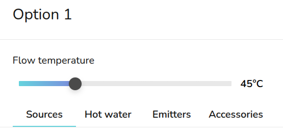
On the right hand sidebar, you can adjust the flow temperature using the slider. From the Sources and Emitters tab, you can view how this affects the heat pump and emitter outputs.
Changes made to the room temperature, ACH and emitters are specific to each design option. Changes will not apply across plans. Navigate back to the surveyed plan to make any changes to your existing emitters. Any other fabric or layout changes can be made from any design option but will apply to all of them. Read more about how design options work.
Sources
To add a heat pump, while on a design option drag and drop a Pump from the left-hand sidebar. Once you have placed these on the floor plan, a menu will pop up to specify the model.
Sound check (UK)
The sound check status can be seen on the right-hand side. Click the ⋯ three dots and then the name of the heat pump(s) where the sound check hasn't been completed.
Read more about selecting a heat pump and completing the sound check.
Hot water
Similarly, to add a hot water storage, drag and drop from Hot water on the left-hand sidebar. A menu will then appear to specify the model.
Read more about specifying hot water storage, including information on domestic hot water calculations.
Emitters
From the Emitters tab, you can see the existing, removed and new emitters for each room. You can click the 🡥 icon on each room to see the full room details.
You can also add room overrides by clicking the exclamation icon and inputting the reason for the override.
To model emitter upgrades follow the steps outlined below.
- To upgrade existing radiators, click on the radiator from the plan and click upgrade. Input the new radiator details and save.
- To replace an existing radiator with UFH, delete the radiator from the floor plan and add underfloor heating by clicking the 🡥 icon on each room. Click Add underfloor heating and input the output and m2.
Read more about emitters.
Accessories
Once you have added both a heat pump and hot water storage, a menu will appear to add any accessories. If possible, compatible accessories will be automatically selected. This step can be skipped.
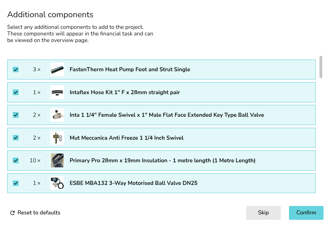
To re-open the accessories menu, navigate to the accessories tab and click + Add Accessories. If you already have accessories selected, click Edit accessories.
If you have further questions, please get in touch on help@heatpunk.co.uk or help@heatpunk.ie.
Material Library and Palettes
This section covers managing your material library. Skip to creating floor plan or back to the rest of the plans task guides.
Managing Your Material Palettes and Library
For each Heatpunk project you will need to use a material palette. This palette defines the u-value and thickness of the walls, doors, floors, ceilings that make up the property you're modelling. You can create default palettes usable on any project via your material library or build palettes from scratch for each project.
Material Library
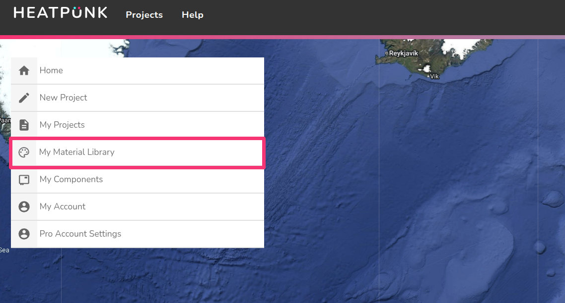
The material library can be accessed from the Heatpunk homepage under My Material Library. This library contains all your material palettes.
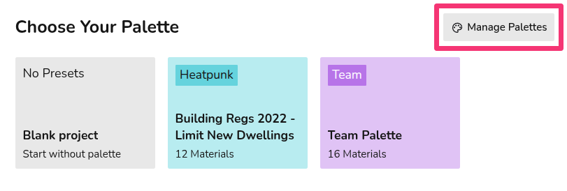
When you create a project, you will see all your complete palettes and the option to create a palette from scratch (No Presets). You can also navigate to the material library from here by clicking Manage palettes.
If you select No Presets and create a palette through a project, it will not save to your material library.
In your material library, you will be able to view and edit all your material palettes and create new ones. Each palette will have a three-dot menu in the top right which will give the following options:
 |
Edit palette Make changes to the palette. This will not affect projects already using this palette. |
 |
Clone palette Make a copy of the palette. |
|
|
Delete palette Remove the palette from your library. This will not affect projects already using this palette. |

See here for information on editing a palette within a project.
In the top right you can create a new palette.
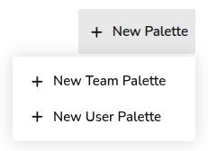
Creating a palette
- Click + New Palette in the top right, then + New Team/User Palette.
- Input the name of the palette and click OK.
- Click on the new palette to add materials.
- For each section (External walls, Windows, etc.) select the materials you would like to be included in the palette.
- Click the star next to the material you'd like to be the default one used for this palette.
- Once you have added all the materials you need to a section, click Next on the bottom right or navigate to the next section directly from the sidebar.
- Once you have entered a material for each section and completed your palette then click Home on the bottom left to finish.
Default materials (starred) are automatically selected in floor plans, but this can be easily overridden or edited on a per-project basis.
You will then be able to select this palette on any new projects. Note:
- Pre-set materials are based on CIBSE's Domestic Heating Guide, if you can't find the material you need, you can create a custom material.
- Some floor materials will not list the u-value. This is because in the MCS calculation, floor U-values are dependent on the area of the room and the number of edges which are external and are calculated per room.
- Standard users will only be able to make user-level palettes. Pro users will be able to create team-level palettes that will be available when pro team members create a project.
Incomplete palettes
Incomplete palettes will save but will not be selectable on projects.
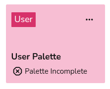
Each section needs at least one material, but only materials used in a project will be displayed on reports. The ! symbol next to each section title signifies that the section is incomplete. Make sure each section has a material, even if you do not plan to use it.

If you have further questions, please get in touch on help@heatpunk.co.uk or help@heatpunk.ie.
Choosing a Material Palette
When you create a project, you will be prompted to select a material palette. This palette determines the composition of the walls, floors, windows, doors and radiators that can be used within a project.
Click on each palette to preview what materials are selected for each section (External Wall, Internal Wall, Floor, etc.). You will be able to make adjustments to the selected palette from within the Plan task. Once selected, click Use Palette in the bottom left.
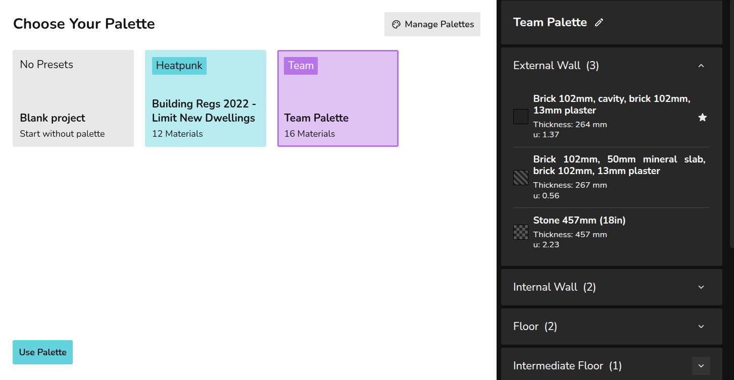
If you select No Presets, you can build a palette from scratch but this will not save to your material library. Click Manage palettes in the top right to navigate to your material library to create default palettes or edit existing ones.
Using a palette in a project
When creating your floor plan, the default (starred) materials will be used for each external wall, internal wall, floor, etc. Each material has a key (patterned square) so you can see where each is being used in the floor plan.
Click on each component to view the full material details and make changes.
Editing palette within a project
Click Close in the bottom left to save these changes.
If you have further questions, please get in touch at help@heatpunk.co.uk or help@heatpunk.ie.
Custom Materials
When creating or editing a material palette in Heatpunk, you have the option to create custom materials. This includes custom walls, floors, roofs, doors, windows and radiators.
Custom materials
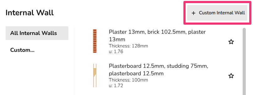
To create a custom material, first start by creating a material palette. Select the relevant section (External walls, Windows, etc.), then in the top right you will see the option to create a custom material.
There are two options when creating your own material (excluding radiators):
- Build layers (only for walls and roofs)
- Enter U-value
Custom radiators use information from the relevant datasheet.
After creating a material (steps below), make sure to select it on the palette and star it if you'd like it to be the default material used for that section.
Managing custom materials across palettes
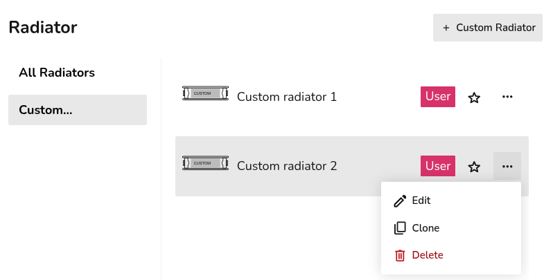
You can view all custom materials you've created across palettes from within a material palette, in the final section on the left-hand sidebar called Custom. Click the three-dot menu on the custom material to edit, clone or delete it. Existing projects are not affected by any changes made here.
You can only view the custom materials that are within the scope of the palette. For example, if you're creating a team level palette, you will only be able to view team custom materials. Follow the steps below to view and use all custom materials.
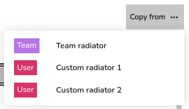
When creating a new custom material, you can also copy the details from existing materials using the Copy from in the top right. Here you will be able to see all custom materials (user and team level) regardless of the scope of the palette being viewed.
Step-by-step
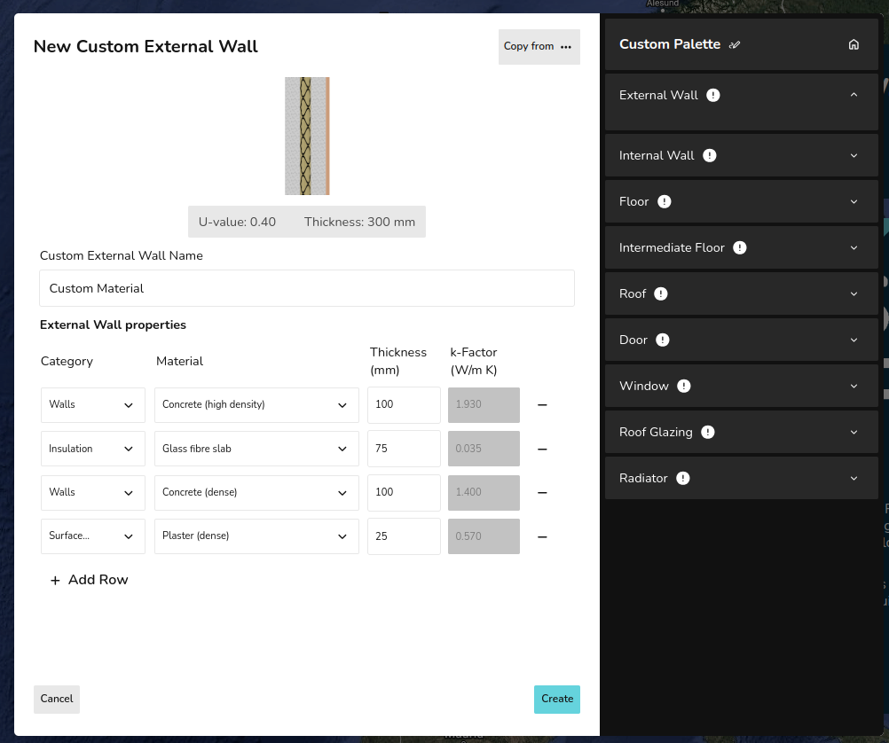
Custom material using Build layers
This option is available for custom walls and roofs:
- Input the name for the custom material.
- Select category of material from the drop-down.
- Select material from the drop-down.
- Input thickness of that layer.
- Add row and repeat from step 2 to 4 until each layer is created.
- Click Create in the bottom right.
For each layer, Heatpunk will then calculate the k-Factor based on the material and thickness. If you select Custom for the material category, you will need to input this k-Factor yourself. The overall thickness and U-value of the material is given at the top.
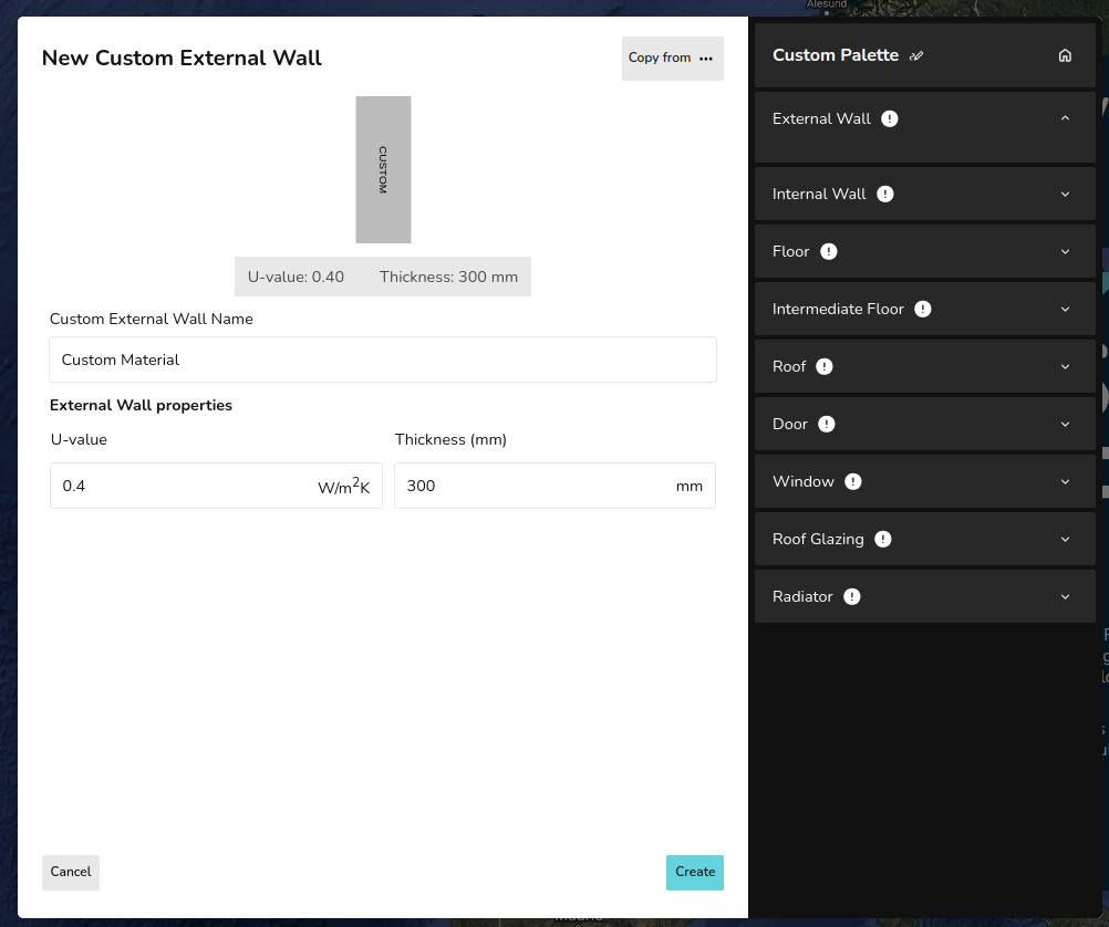
Custom material using Enter U-value
This option is available for all materials (excluding radiators):
- Input the name for the custom material.
- Input the U-value and thickness.
- Click Create in the bottom right.
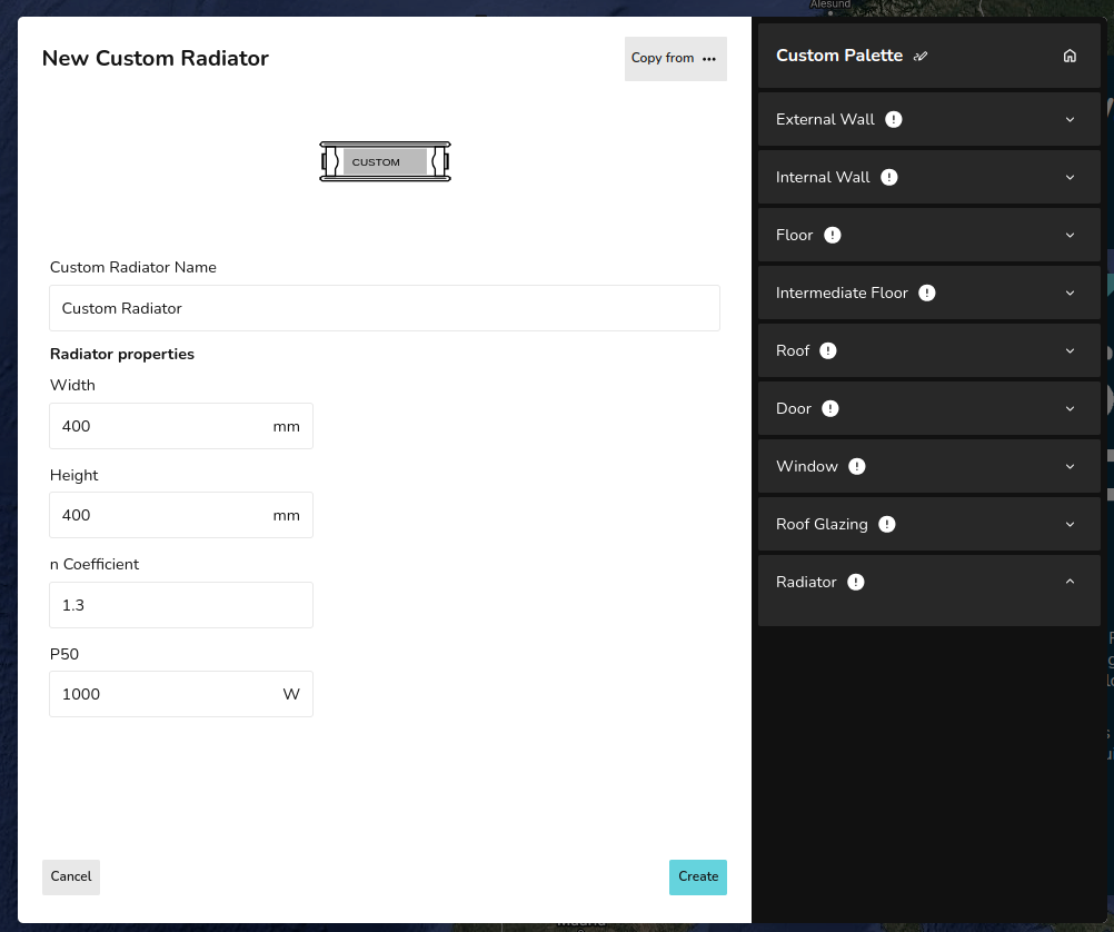
Custom radiators
The default P+, K1, K2, and K3 radiators in Heatpunk are the Stelrad Classic Compact range. If you are not using these radiators, it's important to create custom radiators so the outputs are accurate.
- Input the name for the custom material.
- Input the width and height of the radiator.
- Input the n-coefficient from the datasheet (typically around 1.3)
- Input the P50 for the corresponding radiator size.
- Click Create in the bottom right.
If you have further questions, please get in touch at help@heatpunk.co.uk or help@heatpunk.ie.
Creating a Floor Plan
This section covers the tools needed to create a floor plan - focusing on the surveyed plan.
Go back to material library and palettes or to the rest of the plans task guides.
Creating a Floor Plan
This guide covers an update coming to Heatpunk UK April 27th 2026. Read more about it here. View the old guide here.
The first step in a project is to create a floor plan. The floor plan you build in Heatpunk is used to model the existing state of the property for heat loss calculations, model any emitter upgrades, and specify the location of the heat pump and hot water storage on the plan.
This guide focuses on creating the initial plan, called the surveyed plan. Emitter upgrades, heat pumps and hot water storage also use the floor plan but are modelled in design options, rather than the surveyed plan.
Starting a floor plan
When you create a project, you will be prompted to select a material palette. This determines the materials you can choose from when modelling the property but can be amended at any stage.
You are then prompted to enter the default height for the rooms in the property.
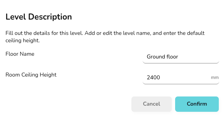
All of these details can be adjusted as you construct your floor plan.
Heatpunk Pro: Speed up creating your floor plan by uploading architectural plans to take measurements from.
Examples
Join our weekly training session for a live example.
Creating rooms

Drag and drop a room from the left-hand menu into position and size to the correct shape. If not using an uploaded floor plan, click the corners of the room to view the dimensions. If using an uploaded floor plan, you can rely on aligning the rooms with the plan below.
Editing room details
Click each room to view the following options:
 |
Change height Adjust the height of the room. Input the height and click the tick to save or the cross to cancel. |
 |
Flue Select whether there is a flue. Choose from: no flue, throat restrictor fitted to flue, no throat restrictor fitted to flue. |
 |
Edit name Change the name of the room. |
 |
Room notes Enter any additional notes about this room, such as customer preferences, pipe routes, etc. These notes will be displayed in the technical report.
|
 |
Select room type Each room needs a type as this determines the ACH, temperature and default name for the room. Select from pre-set options or create a custom room. |
 |
Delete Remove the room from the floor plan |
Note if ceiling regions are added later, they will override height for the room.
On the right-hand side bar, under emitters you can also see each room listed. Click 🡥 See room details. Here you can view the emitter, annual demand, volume, area, heat loss and element heat loss for the room. You can also adjust the room temperature and ACH, as well as add underfloor heating or other emitters.
Adjusting wall properties
Click the walls to view the following options:
 |
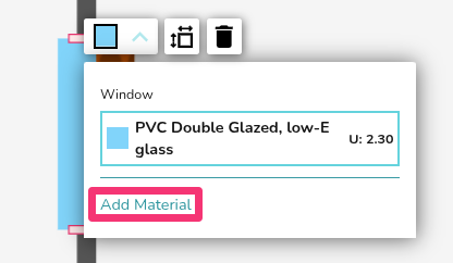
Change material Click to view and select from the material options for this palette. Click Add Materials to adjust the palette. |
 |
External temperature Set the temperature of the region on the other side of this wall. This will default to the ODT and can be adjusted for walls adjoining unheated spaces or neighbouring properties. |
External and internal walls
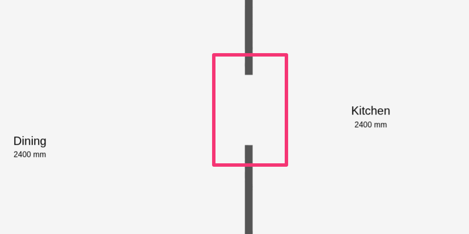
Each wall is either an external or internal wall. This is detected automatically based on whether there is an adjoining room.
As you drag rooms into your plan, it's important that they lock together with existing walls correctly so external/internal walls are correctly identified. Only external walls will have the external temperature setting, external walls are also a darker grey colour.
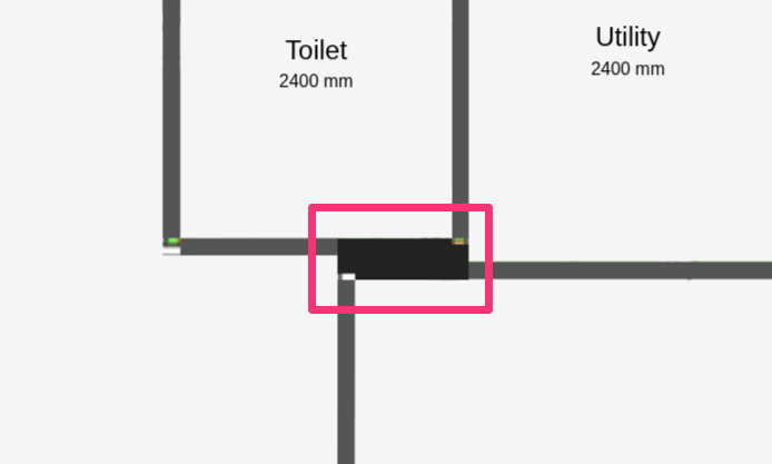
Walls should not overlap and there typically should not be external walls within the interior of a property. Below are some common errors that will lead to errors in the heat loss calculation.
|
Don't overlap walls |
 |
|
Don't leave large gaps between internal walls |
 |
Adding floors
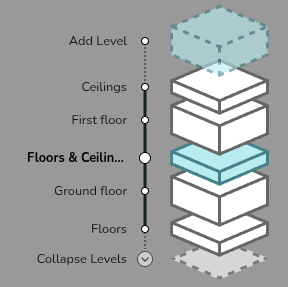
You can add different floors by clicking the transparent box next to Add Level. Move between floors using the expanded view in the bottom-right.
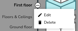
You can change the ceiling height on the whole floor by clicking on the three dots to the right of the relevant floor and selecting Edit. You can also change the name of the floor here. To delete an entire floor, select Delete.
Where the floor and ceiling materials are the default on the selected palette, there is no need to add a region. If the floor and ceiling region has a different material or height to the rest of the space, you can use regions to model this.

Read more on configuring floor and ceiling regions, including adding vaulted ceilings and dormers.
A light grey footprint of the floor below will be displayed, ensure the above rooms are correctly aligned with the floor below. Misalignment will lead to errors in the heat loss.

Adding room components

On the left-hand sidebar you will have the above options. Drag and drop an icon to place the component on your floor plan.
Adding emitters, doors and windows
Drag and drop a radiator, door or window from the left-hand menu into the room and snap it into position on a wall. Click the component to view and adjust the following options:
|
Change material or type Click to view and select from the material options for the selected palette. Click Add Materials to edit the palette. |
|
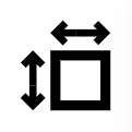 |
Adjust dimensions Input the width and height, then tick to save or cross to cancel. This option will not be available for custom radiators which require a different P50 for each radiator size. |
|
Delete Remove the component from the floor plan |
Internal doors do not need to be included in the floor plan. Rooms with open doorways should typically be modelled as one room.
To add other emitters or underfloor heating, on the room where you want underfloor heating click 🡥 See room details. Then click Add underfloor heating and specify the output per m². You can also see further details on the heat loss calculations in that menu.
For information on emitter upgrades, see Emitters.
Adding heat pump and hot water
Heat pumps and hot water storage cannot be added to the surveyed plan. Create a design option to add these to the plan.
Drag and drop a heat pump or hot water storage option onto the plan. Once you place the heat pump or hot water storage, a menu will appear to select a specific model.
Read more about this in Heat Sources and Hot Water Storage.
If you have further questions, please get in touch at help@heatpunk.co.uk or help@heatpunk.ie.
Pro: Importing Floor Plans
This feature is only available to users with a Heatpunk Pro subscription.

Importing floor plan PDF
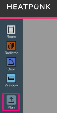
Open an existing project or create a new project and navigate to the floor level you want to upload the plan to. Click on the plan button on the left hand side of the page to upload a plan.
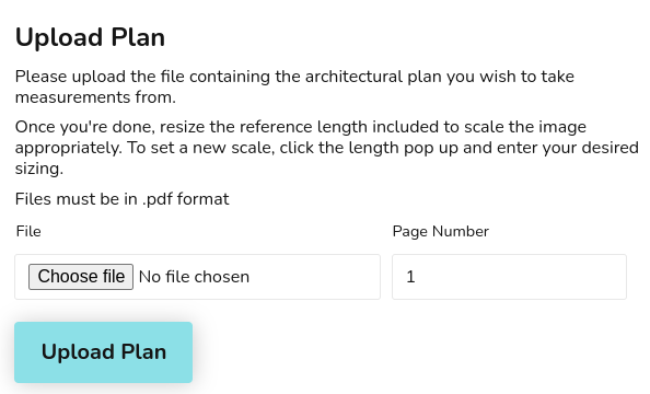
Step 1: Upload the floor plan PDF
Click Choose file to browse the files on your computer. If your file has multiple pages, set the specific page that contains the floor plan you want to use. Click Upload Plan to continue.
For additional levels it's important to align the floor plan with the floor below so heat loss between levels is calculated correctly. See Step 4 for how to do this.
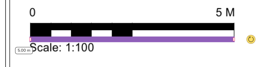
Step 2: Set the scale
Use the purple reference length bar to set the scale.
- Drag the reference length bar over to the plans scale or an object of known length.
- Set the size to match and then click on the dimension to enter the relevant value.

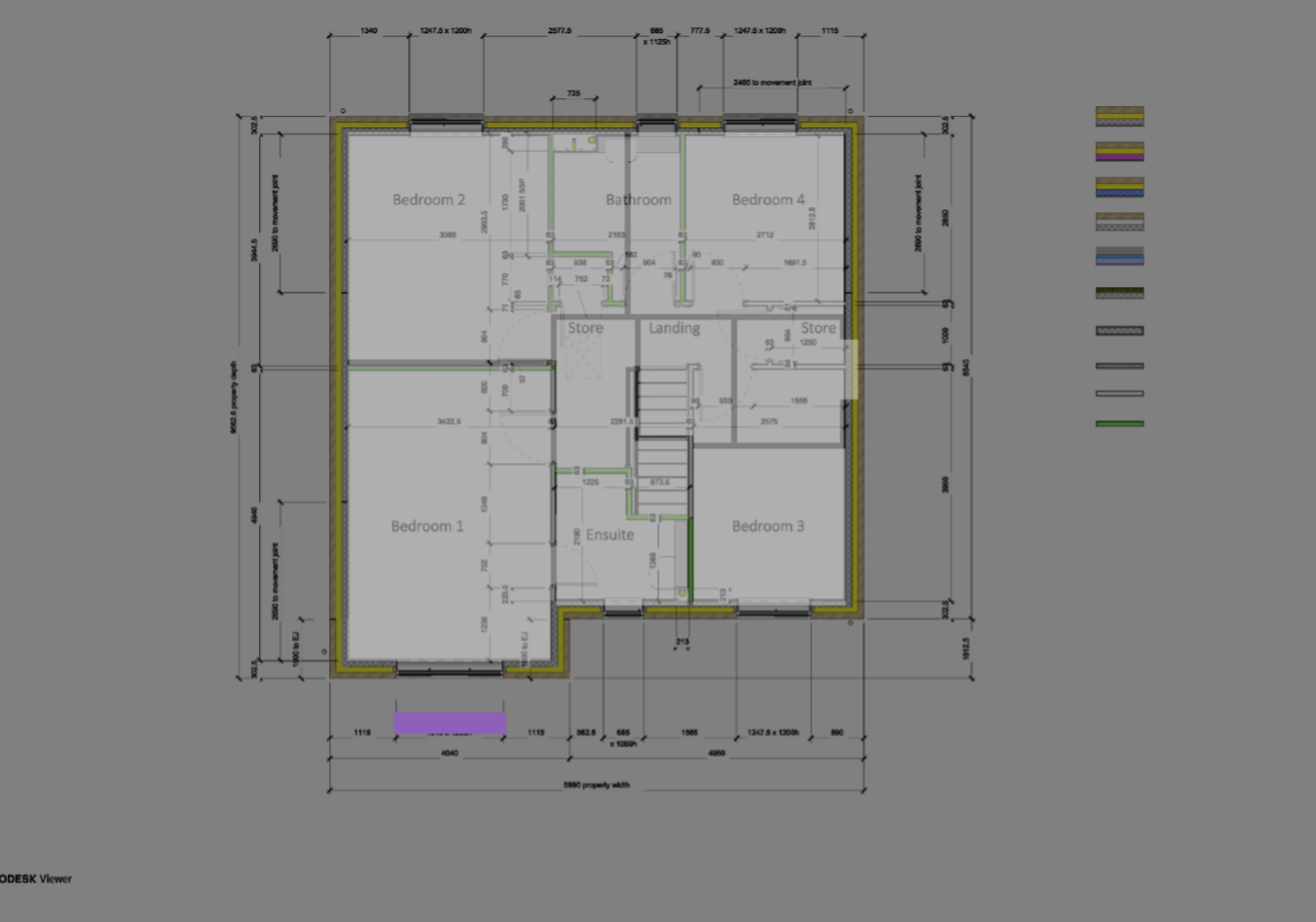
Step 3: Add rooms to floor plan
Drag and drop rooms to build up the floor plan as normal, using the PDF plan as a guide. Read more about creating rooms and floor plans to help with this step.
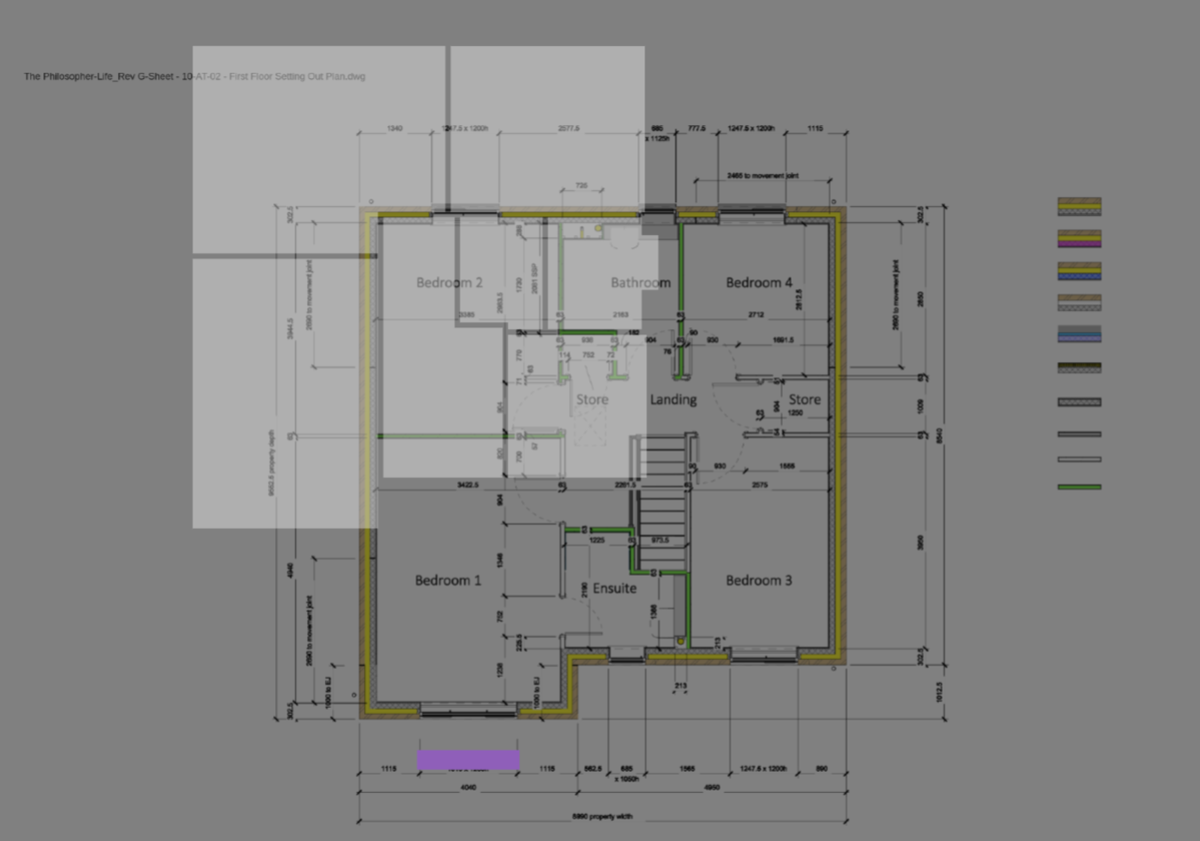
- Click and hold the middle of a room to make the rooms transparent and show the floor plan upload below.
- Click on the walls of a room to turn the transparency off and view the wall and room properties.
Step 4: Repeat for additional levels and align plans
Add level and repeat step 1-3.
After uploading plans for additional floors, ensure the floor plan is correctly aligned with the floor below. Double click and drag to make the plan transparent and display the floor below. You can then align the floors correctly.
|
|
 |
Watch the feature in action
Importing floor plans can massively speed up design time. Watch Angus from our software team use the import feature to create a room-by-room heat loss calculation in under 10 minutes.
If you have further questions, please get in touch at help@heatpunk.co.uk or help@heatpunk.ie.
Creating Rooms
This guide covers how to size a room to the correct shape. For information on adjusting the properties of a room, see Creating a Floor Plan.
Rooms can be dragged and dropped onto your floor plan from the left-hand sidebar
Adjusting shape of room
When creating a room in the plans task, there are a variety of different handles you can use to accurately adjust the shape of a room:
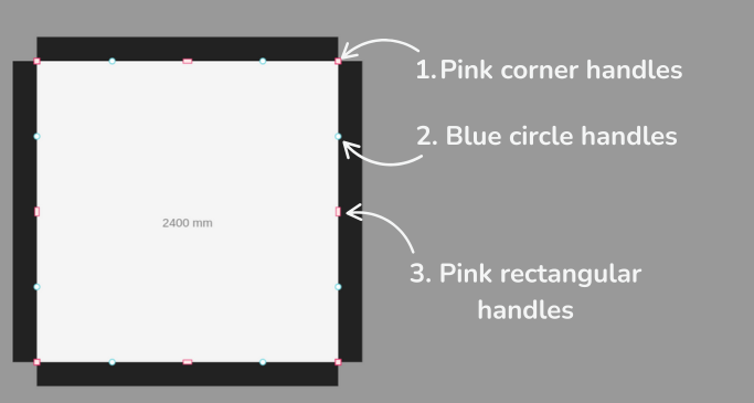
1. Pink corner handles
Click the pink corner handles to show dimensions of the associated walls. You can then click on the values to manually change these.
Click on the pink corner handles to switch between a square and circle handle:
- Use the square corner handles to resize the room whilst keeping the adjacent walls at the same angle.
- Use the circle corner handles to move that point independently of the other points to create angled walls.
2. Blue circle handles
Click and drag the blue circle handles to allow you to split a wall and create irregular shapes. These will then convert to pink handles which you can delete if needed.
3. Pink rectangular handles
Use the rectangular handle to resize the room. Click on the pink rectangular handles to toggle between a square and curved cornered handles:
- Use the square cornered handle to extend a wall out.
- Use the curved cornered handle to extend the adjoining wall independently of the others.
Video demonstration
These tools are demonstrated in the video below.
If you have further questions, please get in touch at help@heatpunk.co.uk or help@heatpunk.ie.
Floor and Ceiling Regions
Heatpunk automatically uses the default material of floors and ceilings defined in your material palette.
Regions are used if the height of a room or material of a ceiling or floor is different from the default. If the height and material are the same across the floor and match the default selected in the palette, you do not need to create a region.
For more information on how this fits into the rest of your floor plan, see Creating a Floor Plan.
Adding a region to change default material
When adding regions, make sure you only have one region covering any given area on your floor plan or this will lead to errors in your heat loss calculations.
Step 1: Navigate to the relevant floor
Step 2: Add the region
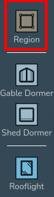
Drag and drop a region in from the left-hand menu. The shape of regions can be edited using the same handles as for rooms (see Creating Rooms).
Create as many regions as are necessary to correctly define each area of the floor/ceiling, as long as they do not overlap regions can be set to cover the entirety of the floor/ceiling or only certain areas. For areas where a region isn't defined, the default material and room height will be used.
Step 3: Set the material of the region
Once you have added a region, click anywhere on it and use the drop down menu to change the material as required.
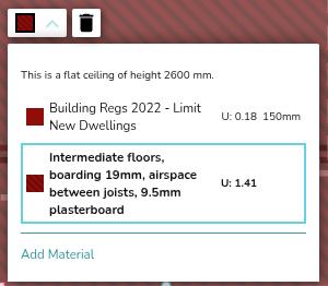
Step 4: Set the external temperature
For the ground floor or top floor ceiling, you should also set the temperature by defining what is on the other side (heated, unheated, ground) of the floor/ceiling. For intermediate floors, Heatpunk will do this for you.
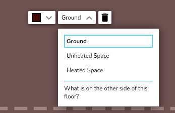
Unheated and heated spaces are taken to be 10°C and 18°C respectively. The ground temperature is based on your postcode.
Adding a region to change default height – vaulted ceilings and dormers
Setting the corner heights of a region overrides the height of the room below. Use this to model a room-in-roof with vaulted ceilings or dormers.
See the video below to learn how to add vaulted ceilings and dormers.
If you have further questions, please get in touch at help@heatpunk.co.uk or help@heatpunk.ie.
Surveyed Plan and Design Options
When you first create a project, you will create a plan of the property as surveyed. This is called the surveyed plan.
Heatpunk allows you to create multiple design options, so you can specify different systems on the same initial floor plan. The surveyed floor plan is used in these design options. In design options, you can place heat pumps, cylinders, and model radiator upgrades.
Surveyed plan
When you first create a project, you must first create the Surveyed plan. This model is the building floor plan as surveyed.
Note that:
- Emitters added to this plan are tagged as existing in the emitters tab.
- Heat pumps and cylinders cannot be added to this plan.
- Design options do not yet support fabric or ventilation upgrades, so these upgrades must be included in the surveyed plan.
After creating your surveyed plan, click Finish surveyed plan to create a design option.
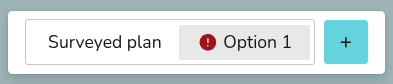
Navigate between the surveyed plan and design options at the top of the page.
Most changes made to the surveyed plan apply to all design options. Read more about this below.
Design option plans
Design option plans allow you to model emitter upgrades and specify kit changes based on the surveyed plan. Read more about this in Sources, Hot Water and Emitters.
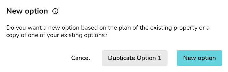
Click the + to add new design options. You can either duplicate and existing option or create a new option based on the surveyed plan.
In the corner of the right-hand sidebar, you can rename, duplicate and delete the selected design option:
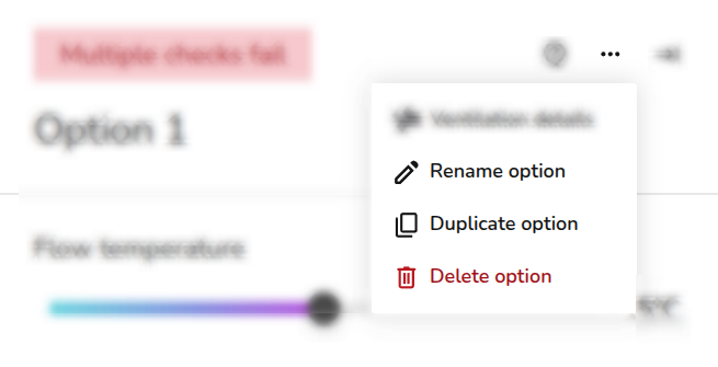
Most changes, excluding building fabric or layout changes, made while on a design option will only apply to that design option. Read more about this below.
After the Plan task, you can only proceed with one design option in forms and reports. Make sure you have the correct option selected before continuing onto the next task.
Editing plans
Some changes apply to all plans and some only apply to the selected plan. Below is a summary of how changes affect the surveyed plan and each design option.
| Changes | Impact on surveyed Plan or design options |
| Emitters | Edits to existing emitters apply to all plans. To upgrade an emitter, delete it and add a new one or click Upgrade on a radiator from within a design option. |
| ODT | Changes to ODT apply across the surveyed plan and design options. |
| Building (walls, floors, windows, doors) fabric and room layout | Changes to room layout or building fabric apply across the surveyed plan and design options. |
| Room temperature and ACH |
Changes to the surveyed plan apply to design options, unless the value has already been changed in that option. Changes to design options only apply to the selected option. Values in a design option appear with a * if they differ from the surveyed plan. |
| Heat pump and hot water storage | Changes to the selected heat pump or hot water storage only apply to the selected design option. |
| Hot water settings | Changes to hot water settings only apply to the selected design option. |
If you have further questions, please get in touch at help@heatpunk.co.uk or help@heatpunk.ie.
Emitters
Emitters are added to a project in the Plan task. Here you can model existing emitters and any necessary upgrades.
Add existing emitters to the surveyed plan and adjust the flow temperature on the right-hand sidebar to clearly see where upgrades are needed. On a design option you can then model these emitter upgrades.
Below is a short video demonstrating how to add and upgrade radiators and underfloor heating.
Emitters tab
As you build your floor plan, you can access a range of controls and details in the Emitters tab:
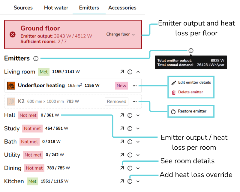
- View heat loss information per floor and navigate between floors
- Emitter output: total floor emitter output / total floor heat loss
- Sufficient rooms: no. of rooms where heat loss is met / no. of rooms where heat loss is not met
- Hover over the 🛈 icon next to Emitters to view the total emitter output and annual demand for the property
- For new or existing emitters, click ⋯ three dots to edit details or delete. On removed emitters click the ⋯ three dots > Restore emitter to add it back to the design option
- Each room displays whether the heat loss is met and the room emitter output / room heat loss
- Click 🡥 to see room details to add other emitters or view the room annual demand, element heat loss, volume and area.
- Click the exclamation icon to override the heat loss for that room
Edits to existing emitters from the Emitters tab apply to all plans. Read about emitter upgrades below.
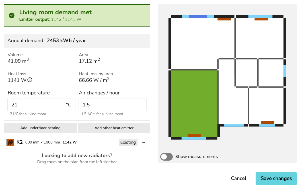
While on the Emitters tab, as you adjust the flow temperature, you can see directly on the floor plan whether the heat loss is being met:
UFH and other non-radiator emitters have a fixed output that does not change with flow temperature in Heatpunk. As seen above, the living room output remains the same.
Adding emitters
You can add emitters in both the surveyed plan and design options. Emitters added to the surveyed plan will be added to all design options, while emitters added within a design option are only added to that option.
Adding radiators
To place radiators on a floor plan, drag and drop from the right-hand sidebar.
Click on the radiator to edit the type and size or remove from the plan. If the type you are looking for isn't listed, click Add Material to add radiators to your material library.
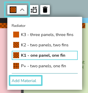
The radiators built into Heatpunk are Stelrad Classic Compacts with Bottom Opposite End connection. If you are using radiators where the outputs differ significantly, you should add them in as a custom radiator. If you are using other varieties of connections for pipework, you must also account for this to ensure the outputs are calculated correctly.
Adding underfloor heating or other emitters
To add underfloor heating, navigate to the Emitters tab and click 🡥 See room details on the room. Below the room details, then click Add underfloor heating or Add other emitters. Fill in the details and then save changes.
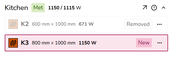
Emitter upgrades
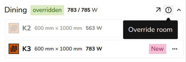
To complete emitter upgrades, make sure you have a design option selected. When you add, upgrade, or remove emitters, this is clearly labelled for each room:
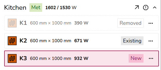
- Existing: emitters added to the surveyed plan
- Removed: existing emitters deleted or replaced on a design option
- New: emitters added to a design option
If a radiator you've added is of the wrong type, remove the radiator, navigate to the correct floor plan (surveyed plan or a design option) and re-add the radiator.
Radiator upgrades
Click on the radiator on the plan and then click upgrade.
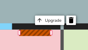

Clicking Save changes will delete the existing radiator from the floor plan and replace it with the new radiator.
Underfloor heating and other emitters upgrades
If you are replacing the radiator with underfloor heating (or another emitter), delete the radiator from the plan and follow the steps above to add UFH/other emitters to a project.
Overriding heat loss
To override the heat loss on a room, click the exclamation icon. Input the reason for the override and save. That text will then display in the technical report.
The text will also appear on the floor plan. To view the full text, click 🡥 See room details.
If you have further questions, please get in touch at help@heatpunk.co.uk or help@heatpunk.ie.
Sources
Adding a heat pump
Heat pumps are added to a design within the Plan task.
While on a design option, drag and drop a Pump from the left-hand sidebar to place a heat pump in the plan. After placing the heat pump, you can select the model. Choose from the recommendations or scroll through the sections on the left, sorted by brand and type (monoblock and split).
When a heat pump is selected, on the right you will see specs, and Midsummer stock levels and pricing. If your account is connected to Midsummer, you will also see your specific pricing.
Sources tab
On the Sources tab, you will see:
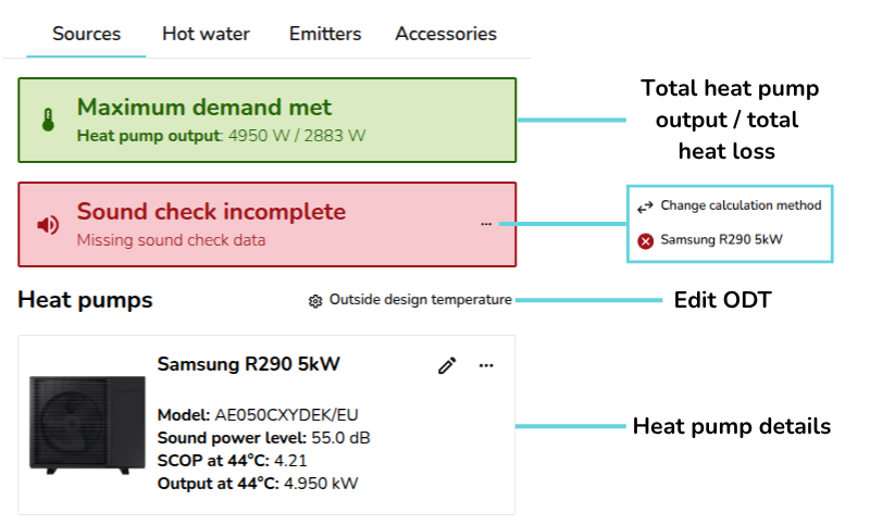
- Total heat pump output / maximum demand
- Sound check information (UK only): choose sound check method and complete sound check for each heat pump
- Outside design temperature (ODT) settings
- Details of selected heat pumps
Heat pumps
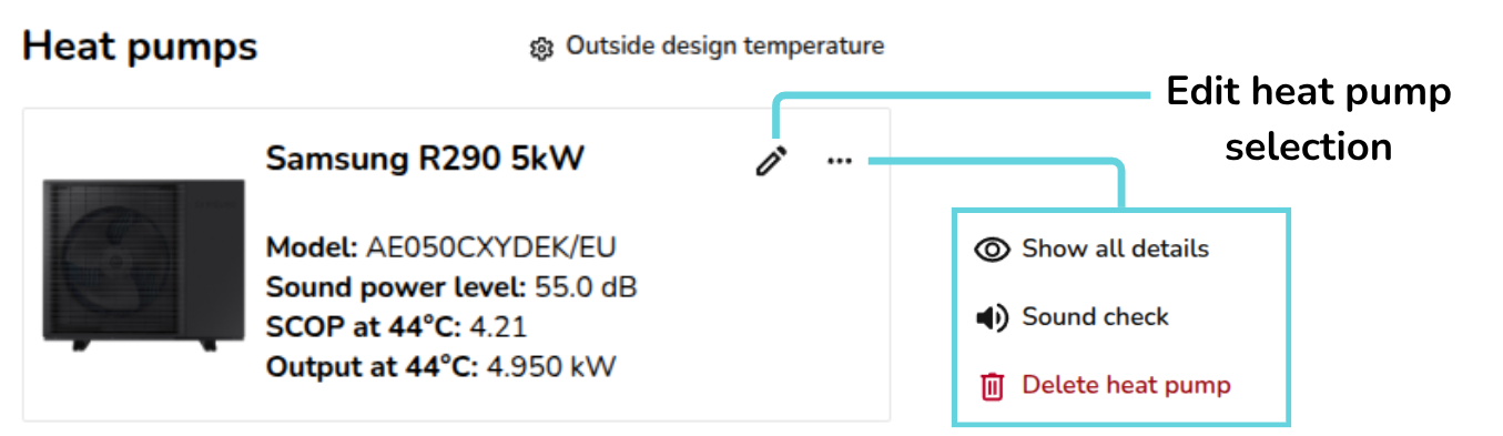
To edit or delete the selected heat pump(s), either delete directly from the design option floor plan or navigate to the Sources tab where you can:
 |
Edit heat pump Re-open the heat pump selector menu to change the heat pump. |
|
|
Show all details Show/hide the nominal capacity and ENA registration number. |
|
|
Sound check Complete sound check for this heat pump. Read more about this below. |
 |
Delete heat pump Remove heat pump from this design option. |


For each heat pump, you can see:
- Model
- Sound power level (dB)
- SCOP at flow temperature
- Output at flow temperature
On the heat pump, click ⋯ (three dots) > Show all details to also display the nominal capacity and ENA registration number (UK).
Adjust the flow temperature at the top of the right-hand sidebar:
Completing the sound check (UK only)
Once you have added a heat pump, you can complete the sound check for that heat pump. On the Sources tab, where it says sound check incomplete, click the ⋯ (three dots) and then the name of the heat pump(s).
Once you have completed the sound check for all heat pumps in the design option, the result will be displayed in the same section:
Sound checks on multiple heat pumps can only be completed using MCS 020 a) (2025 method). Read more about the sound check.
Editing ODT settings
To change the ODT for the project, select ⚙ Outside design temperature next to heat pumps:
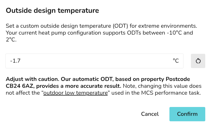
Read more about ODT in Heatpunk.
If you have further questions, please get in touch at help@heatpunk.co.uk or help@heatpunk.ie.
Hot Water Storage
Heatpunk helps you specify a hot water storage solution that's compatible with selected heat pump and sized based on property details. Once selected, you can view specs, domestic hot water (DHW) calculations and Legionella calculations.
You can fine tune these calculations for the specific requirements of the installation and share these details with customer in the technical report and customer proposal.
Adding hot water storage
Hot water storage is selected in the Plan task.
While on a design option, drag and drop hot water storage from the left-hand sidebar to place the hot water storage in the plan. After placing it, you can select a hot water storage option from the recommendations or scroll through the sections on the left sorted by brand and type (pre-plumbed, standard, pre-plumbed slimline, slimline and horizontal).
How are the recommended options chosen?
Recommendations are based on compatibility with the heat pump and are sized according to the number of bedrooms and occupants. Adjust the number of bedrooms/occupants and click Recommend to get updated recommendations.

This is calculated using the MCS method for DHW demand:
Recommended volume = 45 * N
where N is the greater of:
- The number of rooms + 1
- The number of known occupants
When you have an option selected, on the right you will see specs, and Midsummer stock levels and pricing. If your account is connected to Midsummer, you will also see your specific pricing.
Hot water
On the Hot water tab on the right-hand sidebar, you will see:
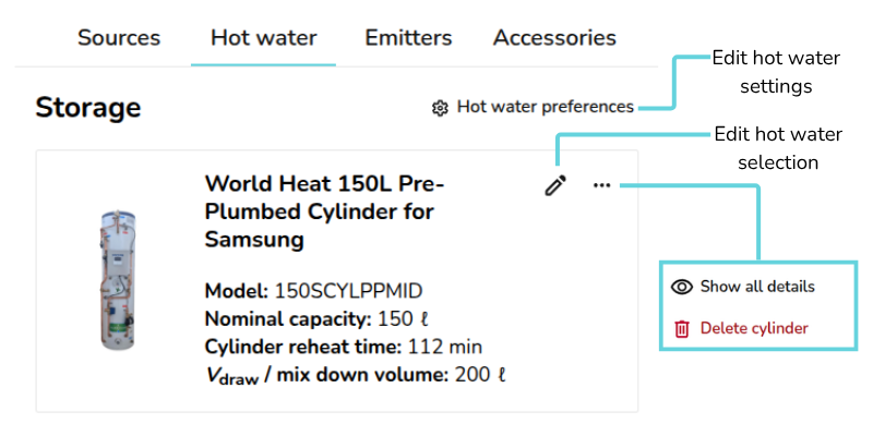
 |
Hot water preferences Edit DHW and Legionella calculations. Read more about this below. |
|
Pencil Edit hot water selection for this design option |
|
|
Show/hide all details Show/hide DHW energy and Legionella purge demand, weight, standing heat loss, coil size and immersion heater power. Read more about these details below. |
|
Delete cylinder Remove hot water storage from this design option |
Hot water storage details and DHW calculations
You can view details for the selected hot water storage in the Hot water tab:
- Model
- Nominal capacity (ℓ)
- Cylinder re-heat time (min)
- Vdraw/Mix down volume (ℓ)
On the cylinder, click ⋯ three dots > Show all details to view the following additional details:
- DHW energy demand (kWh/year)
- Legionella Purge Demand (kWh/year)
- Weight (empty | full) (kg)
- Standing heat loss (kWh / Hrs)
- Coil size (m2)
- Immersion heater power (kW)
This information is then given in the Hot Water Calculations page of the Technical report and Customer proposal for you to share with the customer.
How is DHW energy demand calculated?
DHW energy demand is calculated using the storage temperature, supply temperature, number of occupants and the water needed per person.
First the volume of water needed per year is calculated with the following calculation:
Volume per year = number of occupants * the water needed per person * 365
Noting that for water, volume (L) = mass (kg). Then using the specific heat capacity of water (kJ/kg°C), this is converted to kWh/year:
DHW energy demand = 4.2 * (1/3600) * mass per year * (storage temperature - supply temperature)
Adjusting DHW and Legionella calculations
These calculations can be fine tuned by editing the Hot water preferences on the Hot water tab:
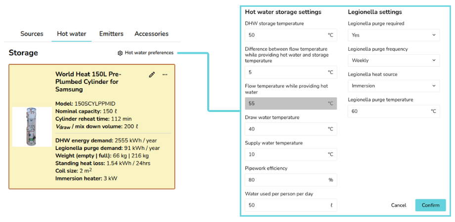
This will give you the following options to edit under Hot water storage settings:
- DHW Storage Temperature (°C)
- Difference between flow temperature while providing hot water and storage temperature (°C)
- Flow Temperature while providing hot water (°C) (This is calculated based on the two previous inputs)
- Draw Water Temperature (°C)
- Supply Water Temperature (°C)
- Pipework Efficiency (%)
- Water used per person per day (ℓ)
Under Legionella settings, you then have these options:
- Legionella purge required (Yes/No)
- Legionella purge frequency (Weekly/Daily)
- Legionella heat source (Immersion/Heat pump)
- Legionella purge temperature (°C)
Changes to these settings will only affect the selected design option.
If you have further questions, please get in touch on help@heatpunk.co.uk or help@heatpunk.ie.
Ventilation Calculations in Heatpunk
This guide primarily applies to the UK version of Heatpunk. For the IE version, S.R.50-2021 (UK Legacy Method) is still the primary method used and will be selected by default. Information on the other two available methods can be found below but disclaimers about MCS and the Legacy method can be ignored.
Choosing a method
Ventilation calculations are completed at the start of the Plan task. In each project will you have the following options:
- Standard method: based on BS EN 12831-1:2017, using assumed values for measured air permeability.
- Measured air permeability: based on BS EN 12831-1:2017, using measured values for air permeability.
- Legacy calculation: based on BS EN 12831:2003.
Standard method and measured air permeability
After selecting either BS EN 12831-1:2017 method, you must then select 'How sheltered from the wind is the building?':

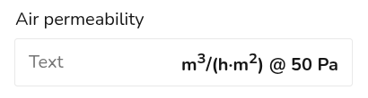
For the Measured air permeability option, you will also be asked to input an air tightness test result:
For the Standard method this value is assumed based on the minimum ventilation rate required for the number of bedrooms in the property.
Heatpunk will then execute the calculation detailed below.
Legacy method
For UK projects, MCS certification in accordance with MIS 3005-D now requires heat loss calculations comply with BS EN 12831-1:2017. Please only select this method when viewing old projects. For IE projects this is called S.R.50-2021 and is still the default option.
If opening a project created before Dec 2025, the Legacy method will be selected. This calculation is a sum of the individual ventilation losses of each room. For each room the following calculation is done:
Room ventilation losses = 0.33 * ACH * Volume * Temperature difference,
where the ACH was taken from Table 3.8 of the CIBSE Domestic Heating Design Guide (2021).
Editing calculation
Once completed, you can edit the ventilation calculation by clicking click the ⋯ three dots in the top right corner and then selecting Ventilation details.
How are ventilation losses calculated?
Under BS EN 12831-1:2017, the ventilation losses for a building are not a simple sum of the ventilation losses for each room. Instead ventilation losses are calculated both at a room level (Equation 17) and then separately on a building (or zone) level (Equation 16):
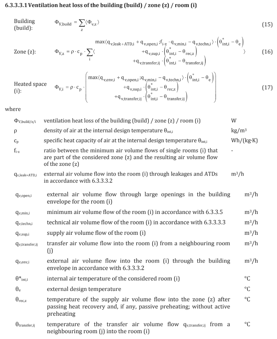
This is because some of the air flow into a room may be pre-warmed from another room. Rooms facing the wind may have cold outside air pushed into them, but then the warm air from those rooms will flow into other internal rooms. This reduces the amount of cold air entering a room not facing the wind, so not all warm air is lost to the outside. This then reduces the overall ventilation heat loss for the building compared to the individual rooms.
What is a zone?
A zone is a group of rooms that are air-connected by design, such as by an internal door that complies with the requirements in Approved Document F: Ventilation, Volume 1 – Dwellings.
Homes are commonly single ventilation zones and Heatpunk assumes a building represents a single ventilation zone.
How does this impact my designs?
- Heat pump sizing: Heat pumps should be sized to meet the overall heat loss for the building. The ventilation losses for the building are generally half the sum of the individual room ventilation losses.
- Heat emitter sizing: The emitter for an individual room must meet the worst case ventilation heat loss. The room ventilation losses are not discounted by the volume flow ratio that is applied to the building as a whole.
Calculation assumptions
Read below for the various assumptions made for the standard and measured air permeability methods.
Standard method assumptions
Where neither a measured air permeability or design air change rate is known, the whole-building air permeability is assumed based on BS 12831 Table B.6 default values.
This uses a value of 12 m³/h.m² @ 50 Pa for all property types.
Measured air permeability assumptions
The air-tightness of the building can be tested using the methodology outlined in CIBSE TM23. The result is expressed in m³/m².hr at a specific pressure difference of 50Pa.
When the building air permeability has been measured, Heatpunk will apply a minimum air change rate of 0.5 ACH to all rooms. This minimum air change rate for habitable rooms is taken from Table B.7 of BS EN 12831-1:2017 and will replace the default values from Table 3.8 of the CIBSE Domestic Heating Design Guide (2021). This approach is intended to more accurately represent the actual air permeability of the building as measured. This may result in lower ventilation heat loss figures than using fixed default air change rates. Fixed default air changes rates can lead to a significant over estimation of ventilation heatloss, especially in older buildings.
You can choose to override the minimum air change rate of 0.5 ACH. Increasing the ACH for a room will only affect its ventilation loss if the ACH yields a larger loss than the loss computed using the measured air permeability.
By using Heatpunk, you are acknowledging and accepting this methodology.
If you have further questions, please get in touch at help@heatpunk.co.uk or help@heatpunk.ie.
Sound Check (UK)
The information provided here does not apply to heatpunk.ie.
The sound check is part of the plan task and helps determine whether the planned installation position will generate excessive noise that could disturb neighbouring properties. The results of the sound check will be displayed in the customer proposal and technical reports.
Completing the sound assessment
There are currently two sound assessment calculation methods published by MCS. Permitted Development Rights in England and Wales require you to use the 2025 calculation method which is based on MCS 020 a). Other UK nations, where they have not changed their Permitted Development Rights, may still require you to use the legacy calculation method based on MCS 020. Please contact your local planning authority if you are unsure which method to use.
The sound assessment is completed in the Plan task. Make sure you have a design option plan selected and a heat pump added to the project.
Click the ⋯ three dots and then Change calculation method to make sure the correct assessment method is selected on the Sources sidebar.
Then follow these steps:
- Click the ⋯ three dots and then the name of the heat pump you would like to complete the sound assessment for.
- Input the details about the heat pump position and assessment points.
- Once you have completed the sound check for all the heat pumps in the project the project, the results will display on the right-hand sidebar under Sources.
To edit the details of the sound check click the ⋯ three dots and the name of the heat pump again.
Using the 2025 calculation method - MCS 020 a)
To comply with MCS 020 a), the calculated noise level at each assessment position must be below 37 dB. Under MCS 020 a), it is vital to include multiple assessment positions, as more distant locations without a barrier may experience higher noise levels than closer positions that are shielded.
In order to comply with MCS 020 a) standard, start by making sure the 2025 calculation method is selected.
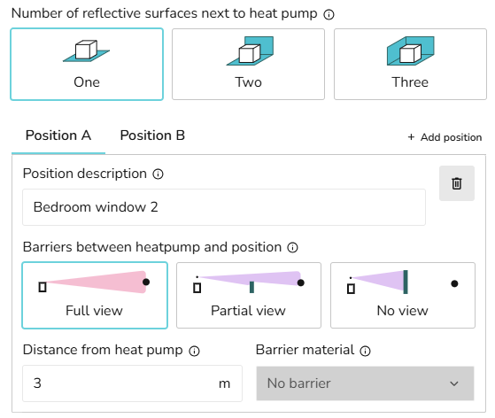
- Select the number of reflective surfaces next to the heat pump.
- Add details for the first assessment position, including the description, distance and details of any barriers.
- Add additional assessment positions by clicking + Add position.
- Delete any positions you no longer need using the dustbin icon.
- Click Confirm to view the sound check results.
See MCS guidelines for further information on the calculation.
Using the legacy calculation method - MCS 020
To comply with the legacy MCS 020 standard, the noise level at a single assessment position must be below 42 dB.
In order to comply with the previous MCS 020 standards, make sure the legacy calculation method is selected.
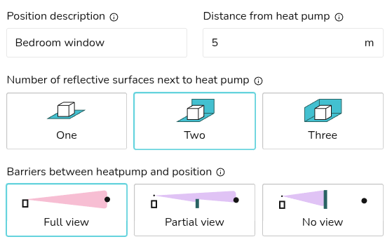
- Add details for the assessment position, including the description, distance, number of reflective surfaces and details of any barriers.
- Click Confirm to view the sound check results.
See MCS guidelines for further information on the calculation.
If you have further questions, please get in touch at help@heatpunk.co.uk or help@heatpunk.ie.