Creating a Floor Plan
Starting a floor plan
When you create a project, you will be prompted to select a material palette. andThis thensets inputthe default material used in the heat loss calculation. Then enter the default height for the rooms in the property. This height can be overriddenadjusted for each room.
If you are a pro user, at this point you can also upload a floor plan PDF to use as a backdrop when creating your plan.
Examples
- Join our weekly training session for a live example.
- Quick demo using the import plans feature.
Creating rooms
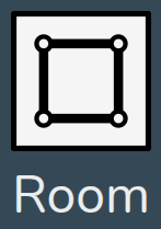
Drag and drop a room from the left-sidehand menu into position and sizeresize to the correct shape. If not using an uploaded floor plan, click the corners of the room to view the dimensions.
Adjusting room properties
Click on each room to view the following options:
 |
Change height Adjust the height of the room. Input the height and click the tick to save or the cross to cancel. This height will be overridden by the height of ceiling regions above. |
 |
Flue Select whether there is a |
 |
Edit name Change the name of the room. |
 |
Select room type Each room needs a type |
 |
Delete Remove the room from the floor plan |
Adjusting wall properties
Click onthe walls to view the following options:
 |
Change material Click to view and select from the material options for this palette. Click Add Materials to adjust the palette. |
 |
External temperature Set the temperature of the region on the other side of this wall. This will default to the ODT |
External and internal walls
Each wall is either an external or internal wall. This is detected automatically based on whether there is an adjoining room.
As you drag rooms into your plan, it's important that they lock together with existing walls correctly so external/internal walls are correctly identified. Walls should not overlap and there typically should not be external walls within the interior of a property. Only external walls will have the external temperature setting, external walls are also a darker grey colour.
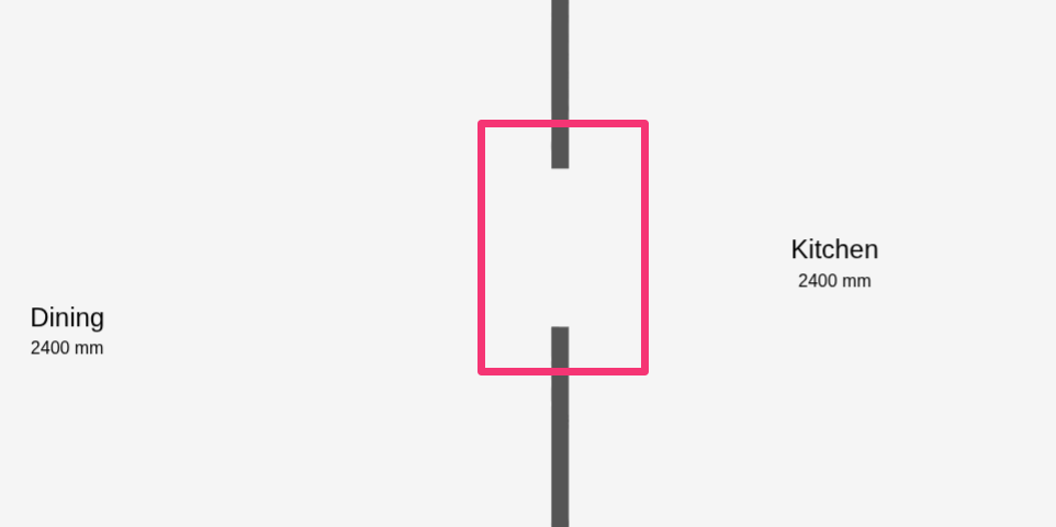
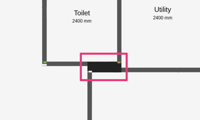
Below are some incorrect examples that will lead to errors in the heat loss.loss calculation.
|
Don't overlap walls |
 |
|
Don't leave large gaps between internal walls |
 |
Adding radiators, doors and windows
Internal doors do not need to be included in the floor plan. Rooms with open doorways should typically be modelled as one room.

Drag and drop a radiator, door or window from the left-sidehand menu into the room and snap it tointo position on a wall. Click onthe the component to view and adjust the following options:
|
Change material or type Click to view and select from the material options for the selected palette. Click Add Materials to edit the palette. |
|
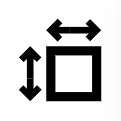 |
Adjust dimensions Input the width and height, then tick to save or cross to cancel. This option will not be available for custom radiators which require a different P50 for each radiator size. |
|
Delete Remove the component from the floor plan |
Internal doors do not need to be included in the floor plan. Rooms with open doorways should be modelled as one room.
Adding floors
You can add different floors by clicking Add Level. Move between floors using the expanded view in the bottom bottom-right.
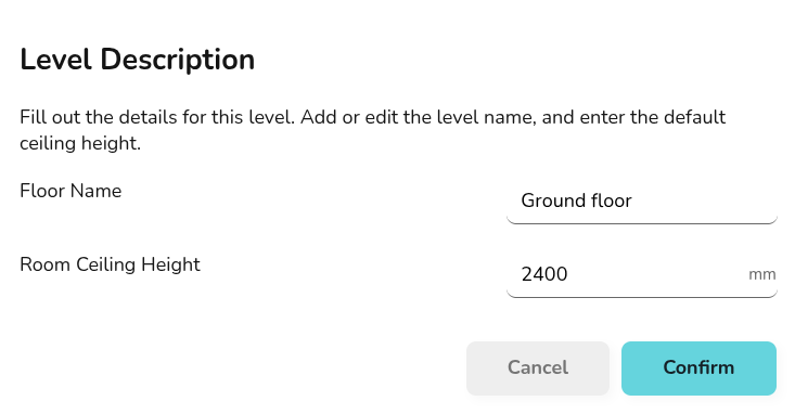
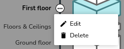
You can change the ceiling height on the whole floor by clicking on the three dots to the right of the relevant floor,floor and selecting Eeditdit. You can also change the name of the floor here. To delete an entire floor, select deleteDelete.
Where the floor and ceiling materialmaterials isare the default on the selected palette, there is no need to add a region. If the floor and ceiling region has a different material or height to the rest of the space, you can use regions to model this.

Read more on configuring floor and ceiling regions, including adding vaulted ceilings and dormers.
A light grey footprint of the floor below will be displayed, ensure the above floorrooms isare correctly aligned with the floor below for accurate heat loss calculations between floors.